3D Graphics Programming with QuickDraw 3D 1.5.4
Previous | QD3D Book | Overview | Chapter Contents | Next |
View Planes and View Ports
As you've learned, QuickDraw 3D provides three different types of cameras, which are distinguished from one another by their method of projection --that is, by their method of generating a two-dimensional image of the objects in a three-dimensional model. A projection of an object is the set of points in which rays emanating from the object (called projectors ) intersect a plane (called the view plane ). The projection created when the projectors are all parallel to one another is called a parallel projection, and the projection created when the projectors all intersect in a point is called a perspective projection. The point at which the projectors in a perspective projection intersect one another is the center of projection.
Currently, QuickDraw 3D provides only normal view planes, where the view plane is perpendicular to the viewing direction.
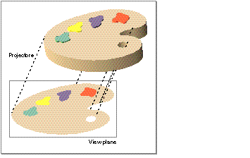
Figure 5 illustrates a parallel projection of an object.
Figure 5 A parallel projection of an object

Notice that, because the projectors are parallel, the size of the two-dimensional image corresponds exactly to the size of the three-dimensional object being projected, no matter where the view plane is located. As a result, you do not need to specify the location of the view plane when using parallel projections. See "Orthographic Cameras" for details on how to specify a parallel projection.
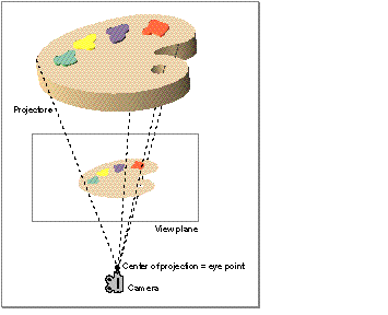
Figure 6 illustrates a perspective projection of an object.
Figure 6 A perspective projection of an object

As you can see, the location of the view plane is very important in a perspective projection. When the view plane is close to the camera, the projectors are close together and the image they create is small. Conversely, when the view plane is farther away from the camera, the projectors are farther apart and the image they create is larger. Similarly, no matter where the view plane is located, the size of the projected image of an object is inversely proportional to the distance of the object from the view plane. Objects farther away from the view plane appear smaller than objects of the same size closer to the view plane. This effect is perspective foreshortening.
When using perspective projection, you therefore need to specify the location of the view plane. QuickDraw 3D provides two types of perspective cameras, which specify the location of the view plane in different ways. See "View Plane Cameras" and "Aspect Ratio Cameras" for complete details on these two types of perspective cameras.
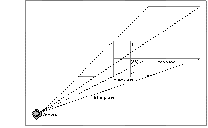
A camera view port is the rectangular portion of the view plane that is to be mapped into the area specified by the current draw context. A draw context is usually just a window, so the view port defines the portion of the view plane that appears in the window. By default, a camera's view port is the entire square portion of the view plane bounded by the view volume (either a box, for parallel projections, or a frustum, for perspective projections). Figure 7 shows the default camera view port for a perspective camera.
You can select a smaller portion of the view plane by filling in a camera view port structure, defined by the TQ3CameraViewPort data type.
typedef struct TQ3CameraViewPort {

    TQ3Point2D                          origin;

    float                               width;

    float                               height;

} TQ3CameraViewPort;
For example, to display only the right side of the view plane, you would set the origin field to the point (0, 1), the width field to the value 1.0, and the height field to the value 2.0.
The image displayed in a draw context is not necessarily the image drawn on the view port. The view port image is scaled to fit into the draw context pane and then clipped with the draw context mask. See the chapter "Draw Context Objects" for information about draw context panes and masks, and for further details on the relationship between a view port and a draw context.
Figure 7 The default camera view port

© 1997 Apple Computer, Inc.
Previous | QD3D Book | Overview | Chapter Contents | Next |